Anatomy of a Line
Anatomy of a Line
Introduction
This essay is best viewed on a desktop or laptop computer. Many interactive elements do not function properly on mobile.
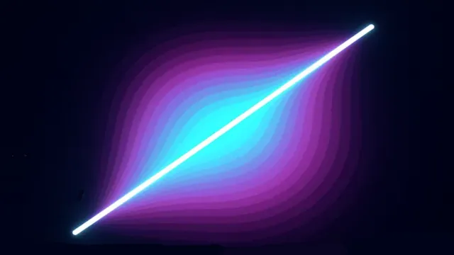
There is a lot more to drawing lines on a computer than it might appear at first. How do you ensure that lines have thickness? How do you render them so they look good at any zoom level, without jagged edges (aliasingAliasing in computer graphics refers to the visual artifacts or “jagged edges” (often called “jaggies”) that appear when rendering diagonal lines, curves, or edges on a pixel-based display. This happens because pixels are discrete units arranged in a grid, but the shapes being drawn are mathematically continuous. When a diagonal line passes through the pixel grid, some pixels must be turned on or off, creating a stair-step appearance rather than a smooth line. Anti-aliasing techniques combat this by using partial transparency and color blending at edges to create the illusion of smoother lines. Common anti-aliasing methods include smoothing edge pixels to intermediate colors or rendering at higher resolution and downsampling.)? And how do you modify a line to give it the exact visual style you want?

At the heart of these questions is the GPUGPU stands for Graphics Processing Unit — a highly parallel processor optimized for numeric workloads (e.g., matrix math). Commonly used for rendering and ML acceleration. and its rendering pipelineThe rendering pipeline (also called the graphics pipeline) is a sequence of stages that process 3D scene data and convert it into a 2D image on a screen. The pipeline typically includes stages like vertex processing (transforming 3D coordinates), primitive assembly (organizing vertices into triangles), rasterization (converting shapes to pixels), fragment processing (calculating pixel colors), and final output (writing to the screen). Modern GPUs implement this pipeline in hardware with both fixed-function stages and programmable shader stages. Graphics APIs like OpenGL, Direct3D, Vulkan, and WebGL provide standardized interfaces to control the rendering pipeline across different hardware. Understanding the rendering pipeline is fundamental to computer graphics programming, as it determines how geometric data flows through the GPU to produce final images.. The way we choose to solve the problem of drawing lines is directly related to how all textures and images in videogames are ultimately rendered onto the screen.
In the rest of this project, I will be discussing what are known as Signed Distance Fields (SDFsSigned Distance Fields (SDFs) are mathematical functions used in computer graphics that calculate the distance from any given point in space to the nearest surface of a shape or object. The “signed” part means the distance is positive when outside the shape and negative when inside it. SDFs are particularly powerful for rendering graphics on GPUs because they allow shapes to be defined mathematically rather than as pixel-based textures. This enables perfectly smooth edges at any zoom level, efficient collision detection, and easy combination of shapes through operations like union, intersection, and subtraction. SDFs are commonly used in shader programming, ray marching, font rendering, and procedural graphics generation.). An SDFA Signed Distance Field (SDF) is a mathematical function used in computer graphics that calculates the distance from any given point in space to the nearest surface of a shape or object. The “signed” part means the distance is positive when outside the shape and negative when inside it. SDFs are particularly powerful for rendering graphics on GPUs because they allow shapes to be defined mathematically rather than as pixel-based textures. This enables perfectly smooth edges at any zoom level, efficient collision detection, and easy combination of shapes through operations like union, intersection, and subtraction. SDFs are commonly used in shader programming, ray marching, font rendering, and procedural graphics generation. is a mathematical function that tells the GPU how far any given pixel is from the surface of a shape. This shape could be a point, a line, a circle, or any arbitrary form you can describe with math. The distance that the SDF produces can then be used to decide what color a pixel should be.
For example we could imagine the surface of a square, where any pixel within 1 unit of the surface would be colored white and any pixel farther than 1 unit from the surface would be colored black. With a SDF shaderIn computer graphics, a shader is a programmable operation which is applied to data as it moves through the rendering pipeline. Shaders can act on data such as vertices and primitives — to generate or morph geometry — and fragments — to calculate the values in a rendered image. that defines the surface of the square, all we would need to check would be: is the pixel within 1 unit of the bounds of the square? If yes color it white, if not color it black. From this simple shader, we would get just the edges of the square.
By combining multiple surface functions, we can build up complex shapes:
- The union of two shapes (combine them).
- The difference of two shapes (subtract one from another).
- Even intersections, where shapes overlap.
These simple building blocks allow us to draw UIUser Interface (UI) refers to the visual elements and interactive components through which a user interacts with a computer program, application, or device. This includes buttons, menus, icons, text fields, sliders, and all other graphical or textual elements that allow users to provide input and receive output from software. UI design focuses on making interfaces intuitive, efficient, and visually appealing. Modern UIs can be graphical (GUI), command-line based (CLI), touch-based, voice-controlled, or use other input methods. Good UI design considers usability principles, accessibility standards, and user experience to create interfaces that are both functional and pleasant to use. elements and textures that scale infinitely. No matter how close you zoom in, or what resolution your screen uses, the shapes are always rendered with maximum possible clarity.
By contrast, traditional textures (bitmapA bitmap (also known as a raster image) is a digital image composed of a grid of individual pixels, where each pixel contains specific color information. Unlike vector graphics which use mathematical formulas to define shapes, bitmaps store the exact color value for every pixel in the image. Common bitmap file formats include PNG, JPEG, GIF, and BMP. Bitmaps have a fixed resolution, meaning they look best at their intended size—zooming in reveals individual pixels and causes the image to appear blocky or pixelated. The file size of a bitmap grows with resolution and color depth. Bitmaps are ideal for photographs and complex images with gradients and textures, but are less suitable for graphics that need to scale to different sizes without quality loss. images) always have a finite resolution. Zoom in far enough and you’ll eventually see the individual pixels. Textures also have another limitation: animation. Any change in their appearance is either drawn frame-by-frame by an artist, or achieved by distorting the existing pixels with math. This makes certain animations hard to design, but with SDFs, we don’t have this restriction: if we can describe the surface with a function, we can animate it mathematically.
Circle
It’s easiest to start with a simple example: the signed distance function for a circle.
A circle is defined by:
- A center point in 2D space (e.g.,
(5, 7)). - A radius (e.g.,
0.5).
In this example, the camera views the scene in the range (-1, -1) to (1, 1) in point space.
On my screen, this circle’s center happens to be at pixel (337, 421) in screen space,
but the exact number depends on your monitor and browser scaling.
It’s important to note the distinction between coordinate systems:
- Screen Space – the actual pixel grid of your display (
x,yin pixels). - Point Space – the
x, ycoordinates of a point in the Euclidean plane, which is mostly for our understanding - TextureIn computer graphics, a texture is an image or data array applied to the surface of a 3D model to add visual detail without increasing geometric complexity. Textures can represent various surface properties including color (diffuse maps), surface detail (normal maps), reflectivity (specular maps), or transparency (alpha maps). Texture mapping works by assigning texture coordinates (typically called UV coordinates) to each vertex of a 3D model, which tell the GPU how to wrap or project the 2D texture image onto the 3D surface. Textures are sampled by shaders during rendering to determine pixel colors. Modern graphics extensively use multiple texture layers and advanced techniques like mipmapping (pre-generated lower resolution versions) to maintain visual quality at different distances and viewing angles. Space – normalized
u, vcoordinates (0 to 1) used to map pixels of a textureIn computer graphics, a texture is an image or data array applied to the surface of a 3D model to add visual detail without increasing geometric complexity. Textures can represent various surface properties including color (diffuse maps), surface detail (normal maps), reflectivity (specular maps), or transparency (alpha maps). Texture mapping works by assigning texture coordinates (typically called UV coordinates) to each vertex of a 3D model, which tell the GPU how to wrap or project the 2D texture image onto the 3D surface. Textures are sampled by shaders during rendering to determine pixel colors. Modern graphics extensively use multiple texture layers and advanced techniques like mipmapping (pre-generated lower resolution versions) to maintain visual quality at different distances and viewing angles..
The GPU ultimately rasterizes triangles in Screen Space with my current vertex shaderA vertex shader is a programmable graphics processing function that runs on the GPU and operates on each vertex of a 3D model during the rendering pipeline. Vertex shaders receive vertex data (such as position, color, texture coordinates, and normals) and output transformed vertex information that will be used in subsequent rendering stages. Typical vertex shader operations include transforming vertex positions from model space to screen space using transformation matrices, calculating lighting per vertex, and modifying vertex attributes. The outputs from vertex shaders are automatically interpolated across the surface of triangles to provide per-pixel values for the fragment shader. Vertex shaders are essential for 3D graphics rendering and are written in specialized shading languages like GLSL, HLSL, or newer alternatives like WGSL. setup, so for this example we’ll stay in that system.
In the code, the circle’s center is represented by the uniformIn shader programming, a uniform is a global variable passed from the CPU to the GPU that remains constant across all vertices or fragments processed in a single draw call. Unlike vertex attributes that can differ for each vertex, uniforms have the same value for every shader invocation during rendering. Common examples include transformation matrices, camera position, light properties, time values for animations, and material properties like colors or texture samplers. Uniforms are declared in shader code and set by the application before drawing. They provide an efficient way to pass configuration data to shaders without duplicating it per vertex. The name “uniform” reflects that the value is uniform (the same) across all parallel shader executions. variable pointA. The distance from pointA to the circle’s edge is defined by edgeDist. Any pixel closer to pointA than edgeDist is drawn light blue; any pixel farther away is black.
There is also a gradient between light blue and black. This gradient is essential:
- If it is too sharp, aliasing appears at the edges.
- If it is too soft, the edges look fuzzy.
- In the example circle, I have set the edge distance and sharpness to equal each other, so the Circle should be maximally fuzzy
The correct sharpness depends on the size of the circle and the current zoom level, so we should change this sharpness as we change the camera’s perspective. As a rule of thumb:
- Increase sharpness for larger shapes (to avoid blurriness).
- Decrease sharpness for smaller shapes (to avoid aliasing).
Finally, note that since pointA and radius are both in Screen Space, we must compute the normalized signed distance. This is done by dividing the raw Euclidean distance (distA) by the radius. The result, sigDist, can be thought of as “what percentage of the radius this pixel lies from the center.”
In order to view what the GPU is calculating at any pixel just mouse over that pixel and the code pane on the right hand side will update with the calculated vectors and colors. You can also click on any line of code in the shader to see what color it would output if we finished on that line. Click anywhere on the main view to reset to the original shader. Right click anywhere on the shader to lock the pixel calcualtion to your mouse coordinates
Definitons of the Variables
| Variable | Description |
|---|---|
vertexColor |
Interpolated RGBARGBA stands for red green blue alpha. While it is sometimes described as a color space, it is actually a three-channel RGB color model supplemented with a fourth alpha channel. Alpha indicates how opaque each pixel is and allows an image to be combined over others using alpha compositing, with transparent areas and anti-aliasing of the edges of opaque regions. Each pixel is a 4D vector. color from the vertex shaderA vertex shader is a programmable graphics processing function that runs on the GPU and operates on each vertex of a 3D model during the rendering pipeline. Vertex shaders receive vertex data (such as position, color, texture coordinates, and normals) and output transformed vertex information that will be used in subsequent rendering stages. Typical vertex shader operations include transforming vertex positions from model space to screen space using transformation matrices, calculating lighting per vertex, and modifying vertex attributes. The outputs from vertex shaders are automatically interpolated across the surface of triangles to provide per-pixel values for the fragment shader. Vertex shaders are essential for 3D graphics rendering and are written in specialized shading languages like GLSL, HLSL, or newer alternatives like WGSL., per-fragmentIn computer graphics, a fragment represents a potential pixel generated during the rasterization stage of the rendering pipeline. When a 3D triangle is rasterized, the GPU creates fragments for each pixel location that the triangle covers. Each fragment contains interpolated data from the triangle’s vertices, including position, color, texture coordinates, and other attributes. Fragments are processed by fragment shaders (also called pixel shaders), which calculate the final color and depth values for each fragment. Not all fragments become pixels in the final image—some may be discarded due to depth testing, alpha testing, or other pipeline stages. The fragment processing stage is where most per-pixel effects like lighting, texturing, and color blending are calculated. input. |
pos |
Interpolated 3D position from the vertex shader (used here as Screen Space x, y). |
fragColor |
Final output color written by the fragment shader (Light Blue). |
pointA |
2D coordinates of the circle’s center (Screen Space). |
radius |
Circle’s radius, used to normalize distance. |
edgeDist |
Distance threshold for rendering the circle’s edge. |
edgeSharpness |
Controls how smooth or sharp the edge falloff is (higher = sharper). |
sigDist |
Signed distance (normalized by radius) between the pixel and the circle center. |
p |
Current fragment’s 2D position (pos.xy) used for distance calculation. |
distA |
Raw Euclidean distance from the pixel to pointA. |
opacity |
Alpha factor from smoothstep, producing smooth falloff at the circle’s edge. |
Line
Okay, so far we have a point and a radius and a signed distance field (SDF) that describes all the pixels within the radius of that circle.
This is about as simple as an SDF shader can get.
The next step up in complexity is to draw a line.
Let’s think for a second: how would we draw a line if we did not have access to the GPU?
To draw a line segment AB on a CPUA central processing unit (CPU), also called a central processor, main processor, or just processor, is the primary processor in a given computer. Its electronic circuitry executes instructions of a computer program, such as arithmetic, logic, controlling, and input/output (I/O) operations. This role contrasts with that of external components, such as main memory and I/O circuitry, and specialized coprocessors such as graphics processing units (GPUs)., we would:
- Compute the slope of the line (rise/run).
- Compute the line length (distance between A and B).
- Start at point A (in screen space), then:
- Plot one pixel at a time, following the slope,
- Move step by step until reaching point B.
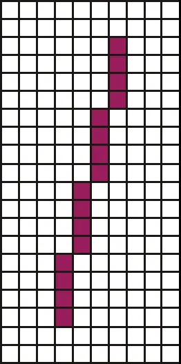
For example: If the slope of 4 and the line length of 20, we would draw 4 pixels in a column, move 1 column to the right, and repeat this process an additional ~4 times until we had drawn the full line.
This step-by-step plotting is how most computer programs are written: we think in terms of what the computer should do next. The GPU flips this paradigm and this inversion is why it is such a powerful computing platform. Instead of thinking step-by-step, we think about what calculation should happen at every pixel on the screen. The GPU runs the same function or program (called a shader) across all pixels simultaneously. Our main bottleneck then, is no longer the math, but the communication between CPU and GPU. This is why the SDF approach is so powerful: it asks the GPU the right question: “how far is this pixel from the shape?” and colors it accordingly, providing us unmatched precesion and creativity.
In the last example we were operating in Screen Space, where the bottom left of the screen is (0, 0) and the top right of the screen is (width of the screen in pixels, height of the screen in pixels). Now I must introduce a new concept that we will keep using for the rest of these drawings: Texture Space, and Scaled Texture Space.
Texture Space is the coordinate system where the bottom left of the texture is at (0, 0) and the top right of the texture is at (1, 1). No matter if we are looking at the quad that the shader is applied to from a different angle or it is skewed or rotated, bottom left is (0, 0) and top right is (1 ,1). This is a powerful concept because it allows us to render the quad in a consistent way in spite of the viewing angle of the camera or any transformations done to the quad.
Scaled Texture Space is a coordinate system that we have to use carefully, and is described in the following manner: the bottom left of the texture is (0, 0) and the top right of the texture is (1, width/height ratio). This coordinate system allows us to take into account the shape of the quad that we are rendering so we can prevent any squishing or stretching on a drawing that will be on a quad that isn’t square. Instead of using this scaled coordinate system, we could either divide our coordinates by the width inside the shader or ensure that we only render square quads.
Both of these options have their own drawbacks. For the first option, because we aren’t in a consistently skewed coordinate system it is easy to mix coordinate systems in our shader code unintentionally and otherwise add a bunch of computation to each pixel. The second option of always rendering a square quad would also work, but we end up needing to discard a lot of the calculation we are doing and get lots of overdraw.
In the example below I have coverted both of the endpoints that make up our line AB into Scaled Texture Space and the coordinate that is being rendered by any one pixel is being provided by the input scaledTextureCoord.
The idea behind this shader is that we take the scaledTextureCoord of the current pixel and then project it on to the vector AB using the dot product. We then use the projection value t to find the coordinate of the closest point on the line to our pixel. Finally we find the distance between this projected point (i.e. the line) and our scaledTextureCoord. After we have the distance it is easy to repeat the smoothstep operation from the circle shader with a much sharper edgeSharpness.
There is one more thing to note and it is a small but important detail. I have setup the interpolation of colors in the shader to match what you would get if you did the color interpolation at the vertex shader level, by using the textureCoord.x value as the value to interpolateInterpolation in computer graphics is the process of calculating intermediate values between known data points. In the rendering pipeline, interpolation is crucial for smoothly varying attributes across the surface of 3D primitives. When vertex shaders output values (like colors, texture coordinates, or normals) at the corners of a triangle, the GPU automatically interpolates these values for every pixel (fragment) within that triangle. For example, if one vertex is red and another is blue, pixels between them will smoothly transition through purple shades. Linear interpolation is most common, but other methods exist like perspective-correct interpolation for texture coordinates. This automatic interpolation allows smooth gradients, realistic lighting, and properly mapped textures without manually calculating values for every pixel. over. We use the Texture Space coordinate here instead of the Scaled Texture Space coordinate because we want the color interpolation to be red at one end of the line and green at the other. To achieve this we need a coordinate that goes from zero to one as we move from the left side of the quad to the right. A vertex shader is a shader that is run once per vertex in the triangle we are rendering. The results are then interpolated between the extremes based on where the pixel is in the triangle. It is common to use the vertex shader to do color interpolation, but we can see in the below result why it isn’t always the best idea. You should notice that pure red or green is not at the segment endpoints point A or B, and not even visible in the output texture, but off to the corner where our shader has cut off the rendering of the line as too far away to be in the SDF. Since there is no color beyond green or beyond red to interpolate from we get the majority of our line as the transition color between red and green. In order to fix this we should probably use the projection value t from the dot product we found earlier to get “how far along the line segment are we?” as a value to interpolate across. In the next example we will fix this.
It is important to remember that computer graphics is not hard because of any conceptual leaps we have to make, it is the confluence of a thousand details that makes something look nice or not, so stick with it.
Definitions of Variables
| Variable | Description |
|---|---|
vertexColor |
Interpolated RGBA color from the vertex shader, per-fragment input. |
scaledTextureCoord |
Interpolated texture coordinate, remapped into Scaled Texture Space (0,0 → bottom left, 1,width/height → top right). |
textureCoord |
Interpolated texture coordinate in Texture Space (0,0 → bottom left, 1,1 → top right). Used here for gradient mixing. |
pointA |
2D coordinates (in Scaled Texture Space) of the first endpoint of the line segment. |
pointB |
2D coordinates (in Scaled Texture Space) of the second endpoint of the line segment. |
inverseLineLengthSq |
Precomputed 1 / |AB|2, used to normalize the projection factor t without recomputing the full vector length. |
widthToHeightRatio |
Ratio of quad width to height. Ensures correct scaling of the line in Scaled Texture Space (avoids squishing/stretching). |
edgeDist |
Distance threshold at which the line edge begins to fade. |
edgeSharpness |
Controls how sharp the falloff at the line edge is (higher = sharper). |
linearGradientColor |
uniform RGBA color used for the gradient blend across the line. |
sigDist |
Signed distance from the pixel’s coordinate to the closest point on the line. |
t |
Projection factor of the pixel onto the line segment AB (clamped to [0,1]). Represents “how far along the line” the pixel lies. |
projection |
The closest point on line segment AB to the current pixel, computed using t. |
opacity |
Alpha factor from smoothstep based on sigDist, providing antialiased line edges. |
fragColor |
Final output fragment color, blended from vertexColor and linearGradientColor with alpha falloff acording to the signed distance. |
Dashed Line
So we now have a shader that renders the simplest line that we can think of, but how do we convey more information with this line? How do we improive our mastery over SDFs and start using unions, intersections and subtractions to get cooler shapes and animations? I think the next logical step is the dashed line, we have some line length AB and we would like to divide it into dashes of length dashLength.
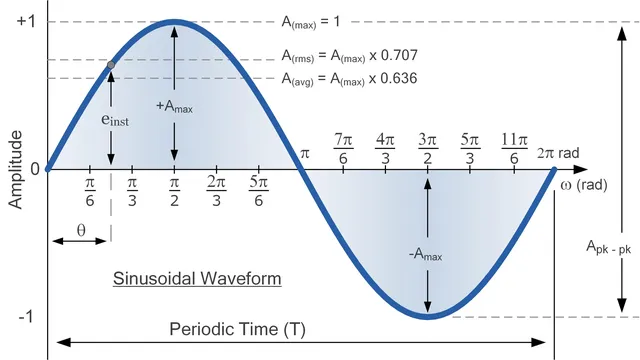
To achieve this we need to introduce the graphics programmer’s best friend the Sine Wave. If you remember from highschool trigonometry the sine wave is a cyclic function that repeats over a period of 2π and loops from 0 to 1 to 0 to -1 and back to 0. The sine wave follows this pattern to infinity so it is extremly useful in getting the computer to draw repeating patterns.
All we need to do then is transform our scaledTextureCoord into radians so that we are operating with the same units as our sine function and shift the sine function’s output to be from 0 to 1 instead of -1 to 1. We need to make this transformation because our opacity is only defined from 0.0 to 1.0.
We also divide the scaledTextureCoord by the dashLength to tell the sine function how many repetitions we want (i.e. how many dashes we want). You can think of this division operation as asigning each pixel to a bucket where the number of buckets is defined by the widthToHeightRatio * 2. The first pixel on the left of the quad should be assigned to the first bucket and so on until we ge to the pixel that is dashLength away from the left origin, let’s call this pixel p2. p2 in order to be assigned to the second bucket must give a value of 2π to the sine function for the loop seams to happen where we want them to. We can repeat this though process of p3 to pN where N is the number of dashes that we can render on the line given the widthToHeightRatio and dashLength. So if we think about pN it should be 2π * N away from the origin to be assigned to the last bucket. I have exposed the float x in the example below to show you the input to the sine function and xBucket to show you which bucket a pixel belongs to where each bucket contains two dashes (one colored and one black). Think of the sine function as repeating every time this xBucket is increased by one.
If we then say that anything below 0.5 is black and anything above 0.5 is colored we can get the dash effect that we want.
The transformed coordinate x that I just described which we are passing to the sine function ranges from 0 to 31.10 in the example shader below which if we convert back to dashes by dividing out the π is 9.89 dashes that we should expect to render (Note that I am refering to the blank spaces between the colored dashes as dashes here as well). And if we divide the quads widthToHeightRatio (5.21) by the dashLength (0.53) we get the same result!
Definitions of Variables
| Variable | Description |
|---|---|
vertexColor |
Interpolated RGBA color from the vertex shader, per-fragment input. |
scaledTextureCoord |
Interpolated texture coordinate in Scaled Texture Space (0,0 → bottom left, 1,width/height → top right). Each fragment represents one pixel’s coordinate along the quad. |
fragColor |
Final output color for the fragment. Initially blended by the SDF, then modulated again by the dash pattern. |
pointA |
2D coordinates (in Scaled Texture Space) of the starting endpoint of the line segment. |
pointB |
2D coordinates (in Scaled Texture Space) of the ending endpoint of the line segment. |
lineLengthSq |
Precomputed squared length of the line segment AB, used to normalize the projection parameter t efficiently. |
dashPhase |
Phase offset (in radians) for the sine wave pattern. Shifts where the dashes start along the line. |
dashLength |
Controls the spatial frequency of the sine wave. Smaller values create more dashes, larger values create fewer, longer dashes. |
edgeDist |
Threshold distance from the line where the alpha fade begins. Defines how wide the visible line is. |
edgeSharpness |
Controls the softness of the antialiased edge transition. Higher = crisper edge. |
linearGradientColor |
RGBA color used for gradient blending along the line segment. Interpolated with vertexColor via t. |
t |
Projection factor of the current pixel onto the line segment AB (clamped to [0,1]). Represents “how far along the line” the pixel lies. |
projection |
The closest point on line segment AB to the current pixel (scaledTextureCoord), computed using t. |
sigDist |
Signed distance between the current pixel and the line’s projection. Used to control alpha fading near the edge. |
opacity |
Alpha factor from the SDF smoothstep, providing a soft edge to the line. |
dashWave |
The sine wave function output (sin(x) + 1) / 2, transformed from [-1,1] to [0,1]. Defines the repeating on/off pattern of dashes along the x-axis. |
dashOpac |
Opacity mask derived from dashWave using another smoothstep, producing the visible dashed effect. |
x |
The transformed coordinate fed into the sine function — in radians. Scaled by dashLength and shifted by dashPhase. |
xBucket |
Normalized index of how many sine cycles have elapsed (x / 2π). Each increment of 1 represents a full colored + blank dash pair. |
Dashed Line Rounded
In the previous example, we successfully created a dashed line using a sine wave. While functional, the result is visually abrupt—the dashes are simple rectangles with hard, flat edges. We can significantly improve the visual quality by giving the dashes rounded end caps.
This is a perfect example of why Signed Distance Fields are so powerful. A rounded dash is simply the union of two different shapes: a rectangle (the body of the dash) and two circles (the caps at each end).
Our strategy will be to conditionally blend these two different SDFs:
- If a pixel is in the “middle” of a dash, we will use the opacity from the sine wave (
dashWave), just as we did before. This creates the flat, rectangular body. - If a pixel is at the “end” of a dash, we will ignore the sine wave’s opacity. Instead, we will calculate the pixel’s distance to the center of a new circle positioned at that end. This will create the rounded cap.
To implement this, we first calculate the standard flat dash opacity (dashOpac) from the dashWave. This is our default.
Then, we introduce new logic to find the centers of the end caps. We use the dashBucket variable (which tells us “which dash we are in”) and the mod operator to find the precise coordinates for the “right-side head” (rDashHead) and “left-side head” (lDashHeadCoord) of the current dash.
With the cap centers defined, we calculate the pixel’s distance to both of them (rDistance and lDistance).
Finally, the if/else if block acts as our “union” operator. It checks if the pixel’s position (using rDashHeadPeriod and lDashHeadPeriod) falls within the region of a dash end.
- If it does (e.g.,
if(rDashHeadPeriod <= 1.)), we overwritedashOpac. The newdashOpacis calculated using the exact samesmoothstepfunction as our main line, but withrDistance(the distance to the circular cap) as its input. We then repeat the same boolean check andsmoothstepfor the left cap as well. - If the pixel is not near an end, the
ifblock is skipped, and the originaldashOpac(from the flat sine wave) is used.
The final fragment color’s alpha is then a product of the line’s SDF (fragColor.a) and our new, conditional dashOpac. This seamlessly stitches the circular caps onto the rectangular bodies of the dashes.
Definitions of Variables
| Variable | Description |
|---|---|
vertexColor |
Interpolated RGBA color from the vertex shader, per-fragment input. |
textureCoord |
Interpolated texture coordinate in Texture Space (0,0 → bottom left, 1,1 → top right). Used here for gradient mixing. |
scaledTextureCoord |
Interpolated texture coordinate in Scaled Texture Space (0,0 → bottom left, 1,width/height → top right). |
fragColor |
Final output color. Its alpha is a product of the line’s SDF (opacity) and the dash’s SDF (dashOpac). |
pointA |
2D coordinates (in Scaled Texture Space) of the starting endpoint of the line segment. |
pointB |
2D coordinates (in Scaled Texture Space) of the ending endpoint of the line segment. |
lineLengthSq |
Precomputed squared length of the line segment AB, used to normalize the projection parameter t. |
dashPhase |
Phase offset (in radians) for the sine wave pattern. Shifts where the dashes start. |
dashLength |
The spatial period (in Scaled Texture Space units) of one full dash cycle (one colored dash + one blank space). |
dashes |
(uniform, unused) Intended to define the number of dashes, but dashLength is used to control frequency instead. |
edgeDist |
Distance threshold from the line center where the alpha fade begins. Defines the line’s radius or “thickness”. |
edgeSharpness |
Controls the softness of the antialiased edge transition for both the line and the circular caps. |
linearGradientColor |
RGBA color used for gradient blending along the line segment. |
t |
Projection factor of the current pixel onto the line segment AB (clamped to [0,1]). |
projection |
The closest point on line segment AB to the current pixel. |
sigDist |
Signed distance between the current pixel and the line’s projection. Used to control the main line’s alpha. |
opacity |
Alpha factor from the main line’s SDF (smoothstep), providing a soft edge to the entire line shape. |
dashWave |
The sine wave function output (sin(...) + 1) / 2, transformed from [-1,1] to [0,1]. Defines the repeating on/off pattern. |
dashOpac |
Conditional Opacity. Initially set by the dashWave, but is overwritten by a circular SDF if the pixel is near a dash end. |
dashBucket |
The index of which dash cycle the pixel is in (e.g., 0.0, 1.0, 2.0…). |
rDashHeadOffset |
Offset (based on edgeDist) used to find the center of the right-side circular cap. |
rDashHeadPeriod |
The pixel’s normalized position relative to the right-side cap. Used as the condition in the if block. |
rDashHead |
The calculated vec2 coordinate of the right-side circular cap’s center. |
rDistance |
The Euclidean distance from the pixel to the center of the right-side cap (rDashHead). |
lDashHeadOffset |
Offset (based on edgeDist) used to find the center of the left-side circular cap. |
lDashHeadPeriod |
The pixel’s normalized position relative to the left-side cap. Used as the condition in the else if block. |
lDashHeadCoord |
The calculated vec2 coordinate of the left-side circular cap’s center. |
lDistance |
The Euclidean distance from the pixel to the center of the left-side cap (lDashHeadCoord). |